- | Home |
- Company |
- Contact |
- News |
- S/ware Eng |
- Standards |
- Academic Support |
- Documents |

- | Requirements |
- Validation |
- RTOS |
- Analysis |
- Software |
- Resources |
- Products |
J-Link JTAG Isolator
-

Phaedsys has now closed
We recommend the Debug Store for all debugging hardware
The J-Link JTAG Isolator can be connected between J-Link ARM and any ARM-board that uses the standard 20-pin JTAG-ARM connector to provide electrical isolation. This is essential when the development tools are not connected to the same ground as the application. It is also useful to protect the development tools from electrical spikes that often occur in some applications, such as motor control applications. A 20-pin flat cable (supplied with J-Link, J-link Pro and the J-Trace) is needed to connect the target.
Features
1kV DC isolation
-
3.3V and 5V target operation supported
-
Powered from emulator and target
-
JTAG standard 20-pin connection supporting TRST, TDI, TMS, TCK, RTCK, TDO and RESET signals
-
Power consumption on target side: < 50mA
-
JTAG frequency: Up to 4MHz
-
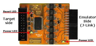
3 LEDs to indicate emulator power, target power and target RESET
Connectors and indicators
The JTAG Isolator uses high speed optocouplers that allow a very low propagation time between input and output. It comes with the following connectors and indicators:
-
20-pin female EMULATOR connector which can be plugged directly into J-Link
-
20-pin male TARGET connector for connection of the target cable
-
Green LED indicating power on the emulator side
-
Green LED indicating power on the target side
-
Red LED indicating RESET
Using the Isolator with J-Link
In order to use the Isolator, follow these steps:
-
Power J-Link.
-
Make sure the green LED on the emulator side is lit. If it is not, follow the instruction in the previous section
-
Connect the target to the target side of the Isolator
-
If the target is powered, the green LED on the target side should be lit
The red LED on the target side is lit when a Target RESET is active (low).
Preparing J-Link to supply power
J-Link needs to supply 5V power to the emulator side of the adapter on pin 19. In order to do this, you may have to configure J-Link once as follows:
Make sure that SEGGER J-Link software is installed on your machine.
-
Start J-Link Commander, which can be found under “Start -> Programs -> SEGGER -> J-Link ARM”
-
Enter the following command: power on perm
-
Plug in the adapter: The LED on the emulator side should now be lit
Using the Isolator with another ARM emulator
The Isolator has been designed for J-Link, but can also be used with other ARM emulators with the same pin-out. In this case, you should make sure that 5V are supplied to pin 19 of the emulator connector and that your emulator is not damaged when applying 5V to this pin. Do this at your own risk!
Phaedsys has now closed |